
exocad’s constantly expanding software solutions contain a leading number of supported lab equipments. It is important to support the newest dental innovations right from the start. That’s why we support our partners, official resellers and dental component manufacturers to make the integration process of new and updated lab equipment systems as easy and efficient as possible.
To enable us to use your data within our software systems, it’s required to form a License Agreement. This License Agreement also allows us to use your company name, trademarks and related imagery/parameters within our software systems for displaying and advertising.
Click here to get more information about the Technology Integration Services.
By integrating 3D printers, articulators, scanners and milling machines into your practice, you can stay at the forefront of dental technology and provide exceptional care to your patients.
Discover your integration options in this short video:
exocad offers a variety of integration options for 3D printers:
These parameters are crucial for customizing and optimizing CAD/CAM workflows in dental technology. They are used to define specific material properties and settings. Click here for more information about Material Configurations.
Printer Presets in the exocad software are predefined settings specifically developed for various 3D printers and their materials. These presets facilitate the printing process and ensure optimal results.
Printer Presets in the exocad software are predefined settings specifically developed for various 3D printers and their materials. These presets facilitate the printing process and ensure optimal results.
Integration process:

ModelWallThickness
Using higher values for ModelWallThickness results in thicker walls, which can enhance the model’s durability but may use more material and increase production time.
Using lower values results in thinner walls, which can save material and reduce production time but may compromise the model’s strength and stability.


ModelShaftGapHorizontal
Using higher values for ModelShaftGapHorizontal increases the horizontal space, which can improve ease of insertion but may reduce stability.
Using lower values decreases the horizontal space, potentially enhancing stability but making insertion more difficult.


ModelShaftGapVertical
Using higher values for ModelShaftGapVertical increases the vertical space, making insertion easier but potentially reducing stability.
Using lower values decreases the vertical space, potentially enhancing stability but making insertion more difficult.


ModelShaftGapHorizontalDynamicDifference
ModelShaftGapHorizontalDynamicDifference allows for dynamic adjustments to this horizontal gap, accommodating variations in the model’s dimensions to optimize fit and ease of insertion.
Using higher values for ModelShaftGapHorizontalDynamicDifference increases the dynamic horizontal gap, which can improve ease of insertion and removal but may reduce stability.
Using lower values decreases the dynamic horizontal gap, potentially enhancing stability but making insertion and removal more difficult.
ModelShaftGapHorizontalDynamicRangeStart
Using higher values for ModelShaftGapHorizontalDynamicRangeStart sets a larger initial horizontal gap, which can improve ease of insertion but may reduce stability.
Using lower values sets a smaller initial horizontal gap, potentially enhancing stability but making insertion more difficult.
ModelShaftGapHorizontalDynamicRangeEnd
Using higher values for ModelShaftGapHorizontalDynamicRangeEnd sets a larger final horizontal gap, which can improve ease of insertion but may reduce stability.
Using lower values sets a smaller final horizontal gap, potentially enhancing stability but making insertion more difficult1.
ModelImplantLabAnalogOffsetHorizontal
Using higher values for the ModelImplantLabAnalogOffsetHorizontal increases the horizontal distance between the lab analog and the implant, which can improve fit but may risk instability. Using lower values decreases this distance, potentially enhancing stability but risking a tighter, less comfortable fit.


ModelImplantLabAnalogOffsetVertical
Using higher values for ModelImplantLabAnalogOffsetVertical increases the vertical distance between the lab analog and the implant, which can improve fit but may risk instability.
Using lower values decreases this distance, potentially enhancing stability but risking a tighter, less comfortable fit.


ModelGingivaMaskGapWidth
Using higher values for ModelGingivaMaskGapWidth increases the gap width, which can make the mask easier to insert and remove but may reduce its stability.
Using lower values decreases the gap width, potentially enhancing stability but making insertion and removal more difficult.


ModelGingivaMaskMinThickness
Using higher values for ModelGingivaMaskMinThickness results in a thicker gingiva mask, which can enhance durability but may use more material and increase production time.
Using lower values results in a thinner gingiva mask, which can save material and reduce production time but may compromise the mask’s strength and stability.


ModelGingivaMaskImplantSupportWidth
Using higher values for ModelGingivaMaskImplantSupportWidth increases the width, which can enhance the stability and support of the gingiva mask but may use more material and increase production time.
Using lower values decreases the width, potentially saving material and reducing production time but may compromise the stability and support of the gingiva mask.
ModelMinimumThicknessAroundPins
Using higher values for ModelMinimumThicknessAroundPins increases the thickness around the pins, which can enhance durability and strength but may use more material and increase production time.
Using lower values decreases the thickness around the pins, potentially saving material and reducing production time but may compromise the strength and stability of the model.
ModelWallMorphologicalClosureDiameter
Using higher values for ModelWallMorphologicalClosureDiameter increases the diameter, which can enhance the model’s structural integrity but may use more material and increase production time.
Using lower values decreases the diameter, potentially saving material and reducing production time but may compromise the model’s strength and stability.


ModelWallBottomSill
Using higher values for ModelWallBottomSill increases the height of the bottom sill, which can enhance the model’s structural integrity but may use more material and increase production time.
Using lower values decreases the height of the bottom sill, potentially saving material and reducing production time but may compromise the model’s strength and stability.


ModelImplantSupportWidth
Using higher values for ModelImplantSupportWidth increases the width, which can enhance the stability and support of the implant but may use more material and increase production time.
Using lower values decreases the width, potentially saving material and reducing production time but may compromise the stability and support of the implant.


ModelImplantSupportGingivaMaskDepth
Using higher values for ModelImplantSupportGingivaMaskDepth increases the depth, which can enhance the stability and support of the gingiva mask but may use more material and increase production time.
Using lower values decreases the depth, potentially saving material and reducing production time but may compromise the stability and support of the gingiva mask.


This tool enables a seamless workflow by transferring designs and related information directly from DentalCAD to the 3D printing software. This includes the transfer of geometries, the number of geometries sent, the printer to be used, material, color, and the rotation of the sent geometries.
exoprint is a module within the exocad's DentalDB, designed to facilitate seamless workflows to 3D printer software, particularly for dental applications.
exoprint provides a *.printRequest file, which is a XML file containing all the necessary data for the 3D printer software.
This is how you can integrate your 3D printer software:
When the 3D printer software is able to read the *.printRequest file, the Technology Integration Team of exocad will add an exoprint button in DentalDB for your 3D printer software. For this button we need following data:
The slicer software then needs to read the information from the dedicated tags:
STL Transfer: The full path to the stl file is stored in the tag “Path”.
<Path>”Path of the STL file”</Path>
Material Transfer: If the slicer software supports presets for different materials and colors, the user can preselect them in the exoprint module. To communicate with the slicer software, we store the Material_Class_Keyword and the Material_Color_Keyword in the tags “Material” and “MaterialColor”.
<Material>Material_Class_Keyword</Material>
<MaterialColor>Material_Color_Keyword</MaterialColor>
Transfer of the transformation matrix: We provide a transformation matrix, that suggests a rotation of the model depending on the part type in the tag “TransformationMatrix”.
<TransformationMatrix>
<_00>-0.99855146955706242</_00>
<_01>0.053804857080292964</_01>
<_02>0</_02>
<_03>0</_03>
<_10>-0.053804857080292964</_10>
<_11>-0.99855146955706242</_11>
<_12>0</_12>
<_13>0</_13>
<_20>0</_20>
<_21>0</_21>
<_22>1</_22>
<_23>0</_23>
<_30>0</_30>
<_31>0</_31>
<_32>0</_32>
<_33>1</_33>
</TransformationMatrix>
The scanner manufacturer provides us with sample files, representing the scan output as 3D files. Our team carefully reviews these files to evaluate their compatibility and ensure they meet our integration standards.
After assessing the files, we determine if the output data is suitable for integration. If so, we provide the manufacturer with detailed specifications outlining the integration process, including required file formats, configuration details, and best practices.
The scanner manufacturer then handles the integration process, implementing the specifications in their software. At the end of this stage, various outcomes are possible:
This workflow ensures a smooth and flexible integration process, catering to various manufacturer needs while maintaining high standards of usability and interoperability.
We provide a variety of integration possibilities for milling machines within our software solution. Please contact exocad Technology Integration for further information.
Our experts will discuss potential integration solutions.
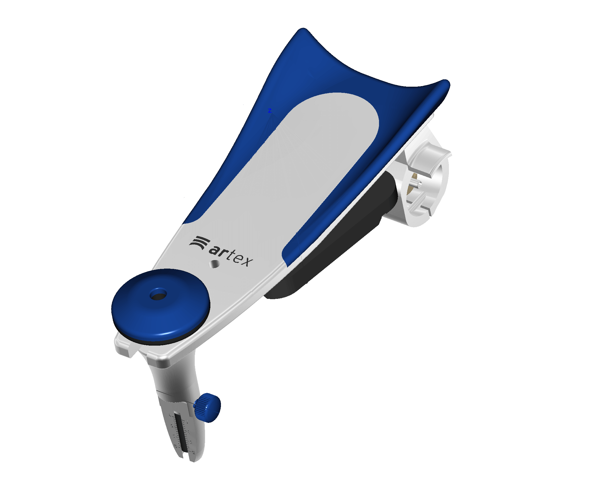
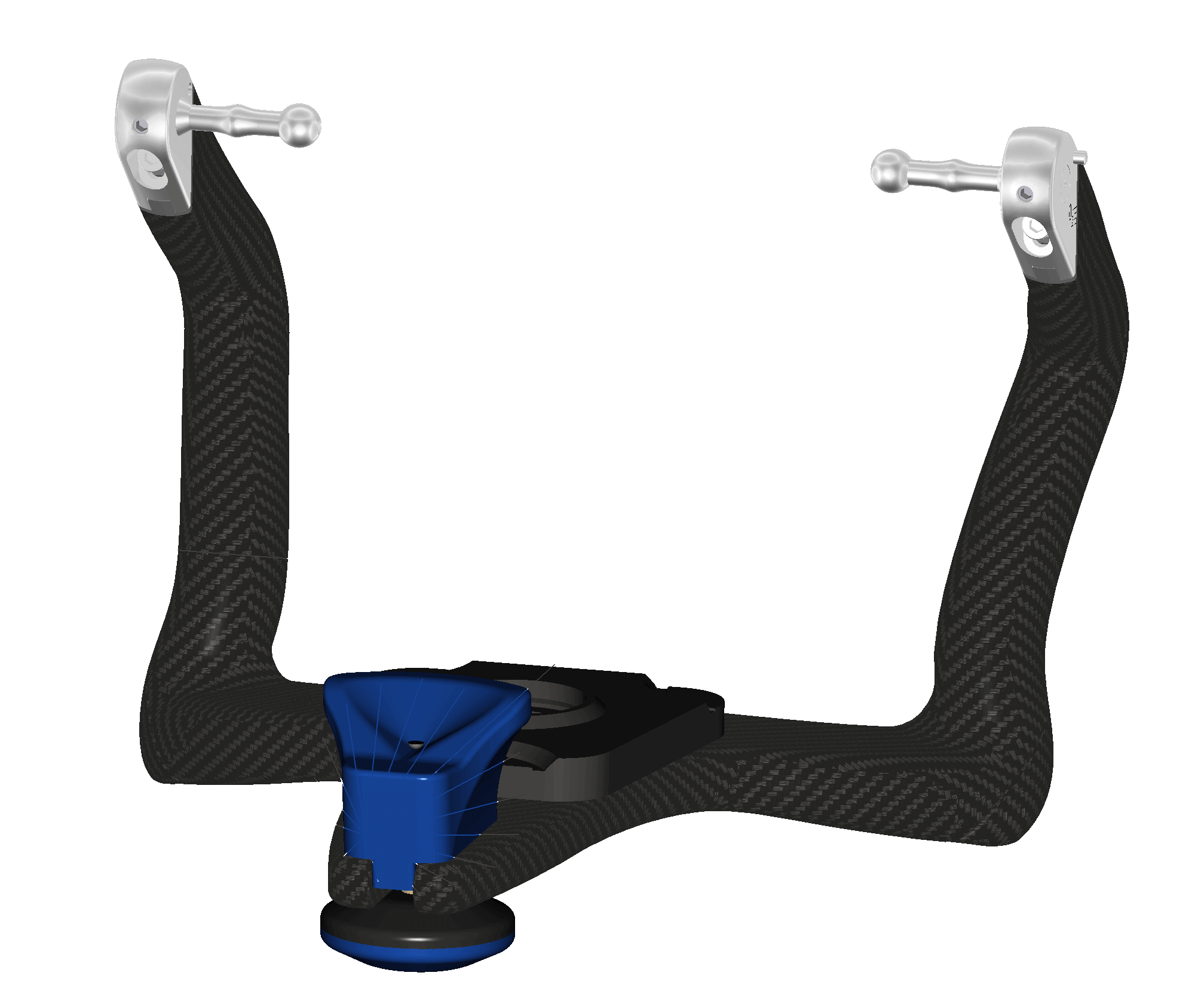
With exocad DentalCAD in combination with the Virtual Articulator Module, you can use virtual articulators to consider dynamic occlusion when creating restorations.
Get in contact with us to discuss the integration possibilities so that your physical articulator receives it`s digital counterpart. As an initial basis for discussion, we need a detailed description of the functionality as well as 3D data of the articulator.
All individual parts within a category should be named according to the schema below:
| Functions Keyword | Color | Numbering | |
|---|---|---|---|
| Example 1: | LowerPartDecorations | grey | 1 |
| LowerPartDecorations_grey_1 | |||
| Example 2: | LowerPartDecorations | grey | 2 |
| LowerPartDecorations_grey_2 | |||
Function Keyword | Function Description |
|---|---|
| CondyleLeftDecorations | Left condyle area |
| CondyleRightDecorations | Right condyle area |
| UpperPartDecorations | Upper frame |
| LowerPartDecorations | Lower frame |
| IncisalNeedleDecorations | Incisal pin |


The Technology Integration team is committed to providing top-notch services and fostering strong partnerships. We're here to support you every step of the way!